|
Portable Coilgun
Construction
|
||||||||||||
| Capacitor 1500 uF 250 VDC, max surge 275 VDC ½ * C * V² = Joules ½ * 1500exp(-6) * 250² = 47 Joules The
TRW site in
Manhattan Beach California sponsors a traditional Swap Meet on the last
Saturday of each month, which
features all matter of sellers ranging from ham radio to computer
products, old and new. One gentleman sells these photo caps by
the
bucket full for
less than .50 cents each. His motto is, "The bigger the pile, the
bigger the smile."
Banks 47J and 94J Banks 375J |
||||||||||||
|
Coil
Coils are wound by hand around a steel rod, which also is the projectile source material. This arrangement achieves very close, 0.5 mm, projectile - coil coupling. A few layers of tape around the rod prevents tight fitting. Generaly, coils undergo a strong contraction force during circuit discharge. However, these coils retain a constant coupling because cyanoacrylate super-bonder adhesive is applied to each layer. Many redeeming values come forth from such an implementation. Barrels where the strength spans from weak paper rolls, metallic, to glass will neither compress nor shatter. Coils are consistent, do not unravel, and need no large amounts of tape to hold together. And internal coil vibration is suppressed to nearly zero. Materials: * 18 - 22 AWG stranded and magnet wire * Super-bonder adhesive penetrating * Super-bonder adhesive thick |
||||||||||||
|
Detector-contact
The housing is a wooden dowel sized to match coil diameter. The four linear gauges excepts two V-shaped metal springs. The metal is procured from a mechanical ink pen. This simple mechanical contact reduces the component count down to a current limiting resistor. Materials: * Wooden dowel * Spring metal * Current limit resistor |
||||||||||||
|
Detector-photo
The IR diode's excess epoxy is sliced off to permit the diodes to be glued onto a small coil. This prevents the diode's protrusion into the coil's inner diameter hole and outer surface area. IR-phototransistor (RX) has a opaque coat for shielding against ambient light. IR-LED (TX) does not benefit from an opague coat and is left as is. Materials: * IR-phototransistor * IR-LED * Wire, header pins, and heatshrink tubing * Super-bond adhesive thick |
||||||||||||
| Voltage
Charger-Boost Converter Lengthy charge time is a thing of the past thanks be to this DC powered 250-900 VDC generator. I tested this by charging (2) 450v capacitors in series and 1,2, and 3 of these 900v banks in parallel. Present boost converter frequency is operating near 3KHz. Materials: * Oscillator NE555 timer * Oscillator support: resistors, capacitors * Voltage regulator LM7812 * Inductor * Switch IGBT 1200V @ 20 A rms * Diodes (1) 1000V @ 12 A rms, 120 A surge FRED (Fast recovery) * Battery pack 1.2v NiMH rechargable (20)  Materials: ACG BOOSTER 3 * Oscillator NE555 timer * Oscillator support: resistors, capacitors * LEDs * Transistor 2N3904 * Voltage regulator LM7809 * Inductor 30 tuns, 3-4 layers, 22awg magnet wire * Switch IGBT 600V @ 40 A rms T0-220 or D2Pack * Diodes (1) 1000V @ 12 A rms, 120 A surge FRED (Fast recovery) * Battery pack 12v-24v lead acid or AA NiMH 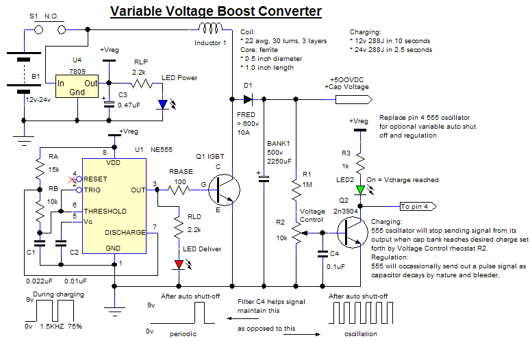 Materials: ACG BOOSTER 3 variant * Oscillator NE555 timer * Oscillator support: resistors, capacitors * LEDs * Comparator LM393 * Voltage regulator LM7809 * Inductor 30 tuns, 3-4 layers, 22awg magnet wire * Switch IGBT 600V @ 40 A rms T0-220 or D2Pack FGB40N62S * Diodes (1) 1000V @ 12 A rms, 120 A surge FRED (Fast recovery) * Battery pack 12v-24v lead acid or AA NiMH 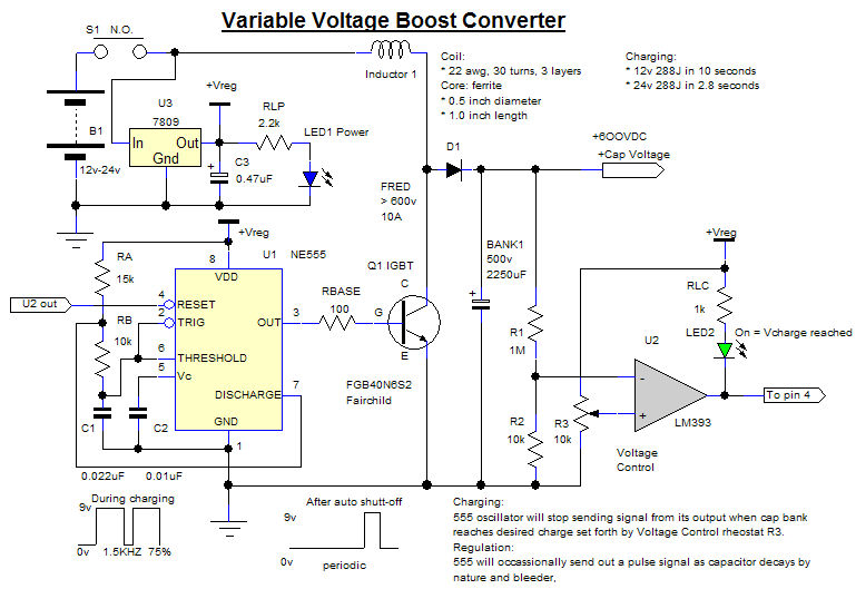 |
||||||||||||
| Diode The diodes are placed anti parallel across each coil. This arrangement protects both the capacitor and the silicon switch from the induced high reverse voltage (back emf) when the coil current has ceased by snubbing the emf down to (-.7v). In actuality the voltage across a bank after a discharge is from 10v - 15v using no resistors in series with the diode. With a series resistor the voltage across a bank varies from 5v to -20v depending on the resistor's value from 1 ohms to 10 ohms. Materials: * Diodes 1000V @ 30 A rms, 210 A surge Fast Recovery |
||||||||||||
| SCR
Bank If an individual SCR does not suffice or survive the subjected pulse currents, other SCRs constructed in parallel increase the surge current rating. All Anode leads are removed, Cathods soldered together as well as the Gate leads. Then the SCR Anode tabs are soldered. The tabs may be left intact during testing but are cut down to minimize its required PCB space when installed into portable coilguns. ACG 760 usage: Each bank closes the electronic gab between coil and capacitor ground, an energy of 95J from a 450V 940uF capacitor bank. 1000V @ 40A, 520A surge for 10 milli seconds Materials: * SCR Teccor SK040R (3) * Solder & Soldering Iron * Reservoir of cold water * Wire cuters |
||||||||||||
| Mount-Target The
target mount was made to limit the number of screw hole
manifestations in my table. Now only two screws are used to
fasten this mount to a table. Logically of course, all screw
secured targets are fastened to the mount. The mount's entrance
jig holds layers of sheet metal. Because sheet metal is highly
resilient yet bends fairly easy under high pressure, the aperture of
this jig must be small to prevent the bending of the sheet metal to
where it slips away from its housing. The main housing is just
one long wood slab cut into three even sections of 8".
Materials: * Wood slab 1/2" x 5 1/2" x 24" * Screws * BYOPCSM (bring your own potato, can, and sheet metal) |
||||||||||||
| Voltage
Charging-Parallel
Though
the capacitors appear as one bank by their close proximity, they are
electrically isolated into 4 individual banks of common ground and
share a common voltage charger. The diode's function is to permit
each capacitor to charge while not being influence by the potential of
another capacitor. The same is true in either idle or discharge
mode. No capacitor leaks into another, no capacitor knows the
existence of another. Simply said, TO EACH ITS OWN.
During charging, the capacitor of least voltage charges first because its respective diode is the first to be biased. Biased diodes are diodes turned on because the potential difference from anode to cathode exceeds a V(threshold) > 0.5v. The non charging banks have the cathode voltage of its respective diodes greater than its anodes; hence the diode is turned off. These banks remain non charging until the voltage of the charging bank rises to equal the next V(threshold) whatever it may be. Simply said, LEAST FULL FILLS FIRST. In the beginning, man was clue less and hasty. The gift of high voltage rendered him giddy and proud. Then the sudden existence of division distorted all elation into perplexity. After a great head scratching, exhaustion from facial expressions, and pile of exfoliation festered from his nail biting, man stud to his feat and said, "Aha I will charge each capacitor one at a time". All was well for a while until man's natural idiosyncrasy of haste spawned visions of less time. Less time to charge, less physical motion needed for charging, the search for such things brought about bafflement. The usual brain storming ensued until charging by relay had came through. This implementation did reduced the number of physical movements inherent to manual wire swapping. However, the problem of time remained. Fed up with the time problem and replacing burned out relays, man decided to reach deep into his mind to find that which is sublime. Materials: * Diodes (4) 1000V @ 6 A rms, 80 A surge 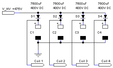 |
||||||||||||
|
Voltage
Charging-Detector
From the lack of patience and board space, I decided to make shift this circuit of readily available parts. This small footprint readiness indicator does not use a comparator but only a few resistors and a transistor. An LED is the charging indicator and illuminates when the capacitors are charged to 500 VDC. A voltage divider feeds a portion of the bank voltage to the base of transistor Q1. The transistor conducts when its base voltage exceeds 0.7v and permits the LED indicator to illuminate. The Rheostat R5 is needed to adjust the actual indicator trip point because resistor values are rarely exact. Yes, R2 may be removed by increasing the rheostat R5 to 2K, but as always the designs are built with components on hand. Materials: Usage ACG 188 * Resistors 1M, 1K, 220 * Rheostat 1K * Transistor 2n3904 NPN * LED Green 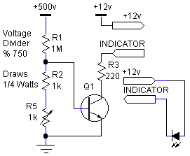
 |
||||||||||||
| Projectile I use
steel rods from common
hardware
stores. Measuring, cutting and pointing the raw steel bits is a
fast process, about 2 minutes a projectile. However, 2 minutes
feels like 20 when being inundated by the loud noise, sparks, and heat
generation associated with forming metal. Polishing a projectile
to a crystal shine, now that consumes a lot of time. Below is the
systematic
process I use governed by the tools I have.
Measure
and mark the rod sections to approximate projectile
length. Cut the rod into raw sections with a saw and metal cut
off blade. Grind one end of the raw bits into a point shape with
the raw bit inside drill/driver and metal sanding blade inside
saw. Press the raw bit onto sanding blade at desired point angle
while bit and sanding blade rotate in counter directions. Remove
any excess length of this bit by grinding down the non pointed side
with a saw and sanding blade. Polish the projectile using a drill
press and sand paper. Alter projectile point angle with the
coarse 60 grit sand paper. Buff the coarse finnish with the 220
grit sand paper. Apply the final shinny coat with the very fine
600 grit sand paper.
Materials * Steel rod * Drill / Driver * Saw, metal cut off blade, metal sanding blade * Drill Press * Sand paper 60, 220, 600 grit |
||||||||||||
Schematic ACG188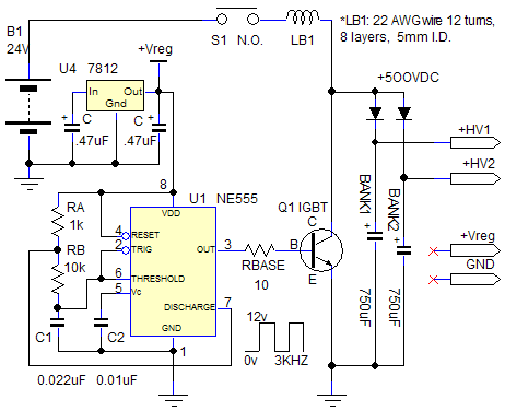 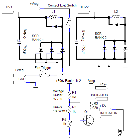 Materials * IGBT 1200v 20A IRG4PH30K "IRF" * SCR 800V 40A 520A surge S8040R "TECCOR" * DIODE 1000V 30A 200A surge DSE130-10A "IXYS" * REGULATOR LM7812 * Q1 2N3904 NPN TRANSISTOR * RESISTORS * LED * TIMER LM555 * CAPACITOR 250v @ 1,500uF * BATTERY 24V NiMh pack |
||||||||||||
| Navigation | ||||||||||||
|
|
||
|
||
|
|
||
|
||
|
||
|
||
|
||
|
||
|
||
|
||